repairs, mods & improvements. * * *
* * *
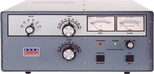
IC8POF's Commander Linear Amplifier
repairs, mods & improvements. * * *
This amplifier has been one of the best workhorses in the Ham RF_PA arena.(*n1)
But as for every thing on this world sooner or later it may happen a failure.
In this page I describe my experiences and solutions with this fine equipment.
=.=.=.=.=.=.
One , but not rare thing happened to this unit: its HV voltmeter did not marked correctly the plate voltage anymore.
Looking at the schematic it revealed that the plate voltmeter resistors were in the Power Supply compartment.
So I decided to open the unit to check if the HV resistors were ok.
What a surprise on opening the chassis.
The PS_DC_Unit was not as usual on the transformer's side of the chassis: rather it is mounted
on the underside of the TUBE's compartment.
It means that to check or change the 3 HV voltmeter resistors one fellow Ham has to open the whole tubes box.
Unusual, but there was no other way for that service. Or I supposed so.
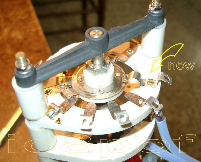
That time I had no idea on how to open the RF box, so I wrote for assistance to Pat Stein
at Command Technologies
He sent to me the two above pics (here the 3 tubes model) to have an idea of how look the whole unmounted RF compartment
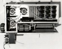
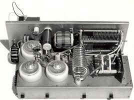
and the suggestion to take out the whole rf box from the main chassis.
Wrong or right I decided to go inside the RF box from the tubes base-plate as it seemed to me easier that way.
The whole procedure of opening the RF box lid could take only 1 hour.
But, as the Devil does NEVER rest, it happened that during the unscrewing of the the band switch 2 things went wrong .
I will describe the accident under the Band Switch affair paragraph in the page below.
Yes of course, but as the common pin of the BS broke itself as if it were of butter
I had to unmount all the parts from the plate.
Read the report below.

Opening the tubes base plate.
From left to right:
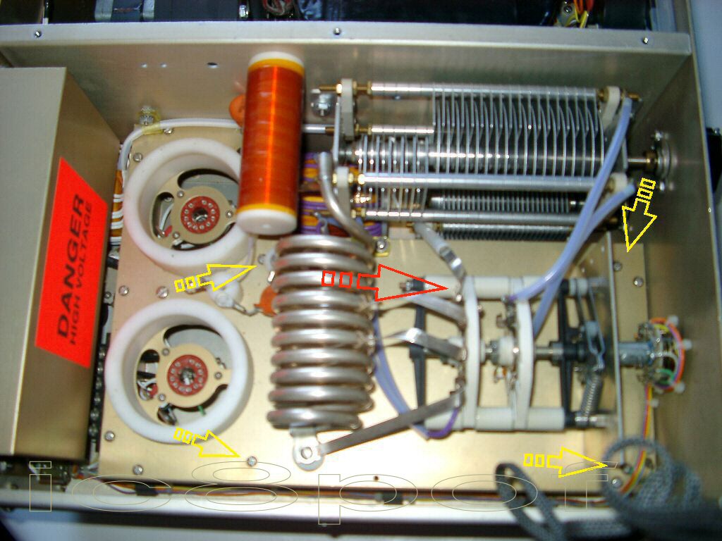
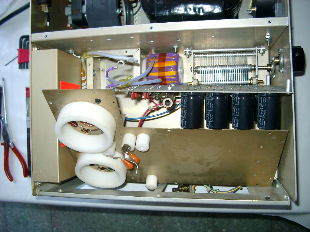
in pic 1 the yellow arrows show the 4 screws holding the power-supply board on the underside
the red arrow shows the common pin that broke itself when attempting to unscrew the flat wire
Don't forget to take the pictures during the unmounting phases.
be very carefull to unscrew the flat copper wire from the common pin marked in red in pic1!
if the band switch common pin brokes itself then read the story in the second part of this article.
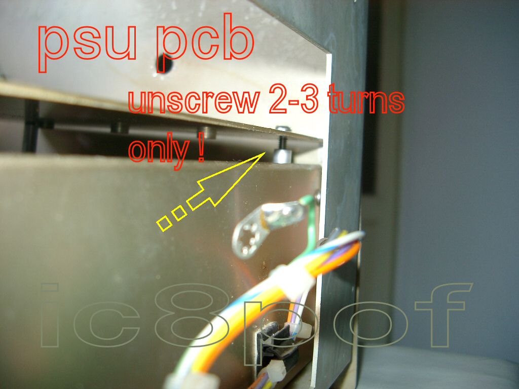
pic2 and 3 show the psu-pcb screws losened to get it out.
Much care must be given here to not uscrew completely the retaining screws
2 or 3 turns are safe to try and get out the psu-pcb, if still too less try to give the 4th turn.


Pic4, I had to unscrew also the left side of the front panel to let the tubes base plate move toward the front a pair of millimetres.
In pic 5 is shown the psu-pcb rotated outside the box. The connecting wires are enough long to do the work, but care must be taken into account.
Measuring and changing the three 1megaohm\2watt carbon resistors is easy.
Now you are ready to go back and reclose the amplifier.
================
Part 1 , the common pin broken .
That is not all , another strange accident was on the way.

The common pin marked in yellow in pic7 simply broke itself when I attempted to unscrew the holding screw of the flat copper wire.
The disappointment was great at that moment, as repairing a broken band switch was a very difficult thing to guess.
After some minutes during which I had scary doubts and thoughts as : sending back the PA or buying a new band switch,

As we say : sleep on it, and something will come in mind, I left all on the table and went away.
The next day, being back into the lab, I was turning the BS in the hands for sometime when a light came on.
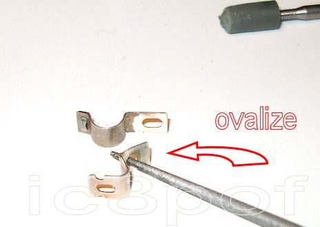
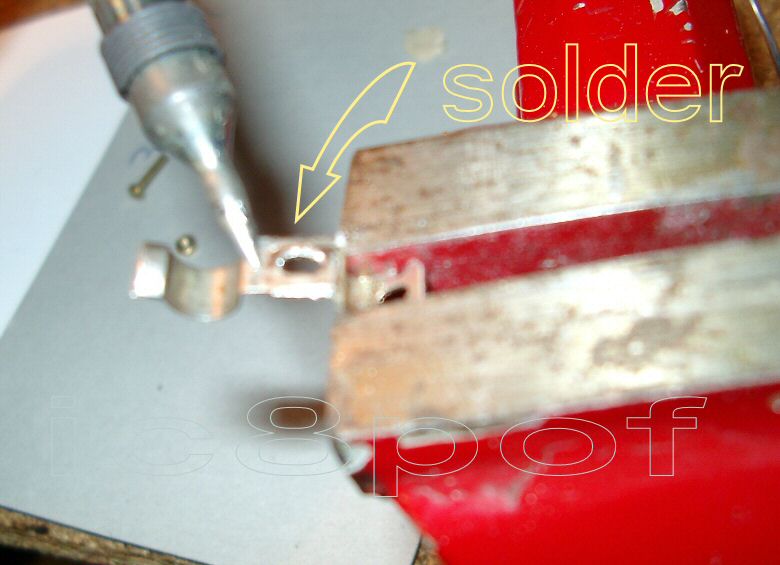
The BS has an unused contact quite near the common pin, marked in red in pic7.
This unused pin can be used to repair the common pin by soldering together the two pins as shown below.
The pin reconstruction puts the band switch again ON AIR.
================
Part 2 , the Band Switch Holding Nut broken.
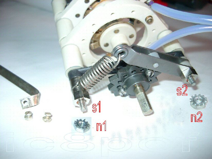
The BandSwitch is held in place by the means of only 2 nut-screws combo, look at pic8 screw1 + nut1 and s2 + n2 .
1) bug description :
The 2 holding screws s1 and s2 in pic8 are too short and S2 is STILL MORE SHORTer !
When I attempted to remove the nut N2 it simply has fallen away from its screw.
Enlarging the pic8 you will see that the grooves on the inside of N2 are quite absent .
As the band switch has a very strong spring and the band latch has high teeth , the strenght required to rotate the shaft
highly stresses the two little holding screw\nuts combo.
More: the nuts are of alluminium . Such material is not god to hold such a stressed mechanical item.
Strange ... as the whole construction is very solid.
2) bug solution :
As the band switch uses american gauge screws\nuts pairs it would be very difficult for me to substitute such items.
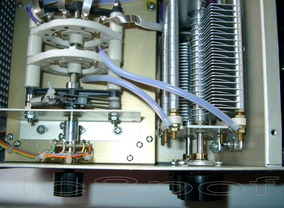
After tweaking around in the lab as usual to get an idea ,I noted that the PLATE Variable Capacitor (PVC) holding screws
inside the amplifier were the same gauge as those on the BS and their lenght were longer than needed.
Take 2 of them about 1 inch long and substitute the s1 and s2 in pic 8.

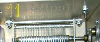
Pic11 shows how the VCs are mounted. Here is shown only the Load VC as the PVC was already out.
Every VC is held in place by 2 screws and 4 nuts : 2 nuts give the spacing from the chassis and the outer 2
fasten the VCs.
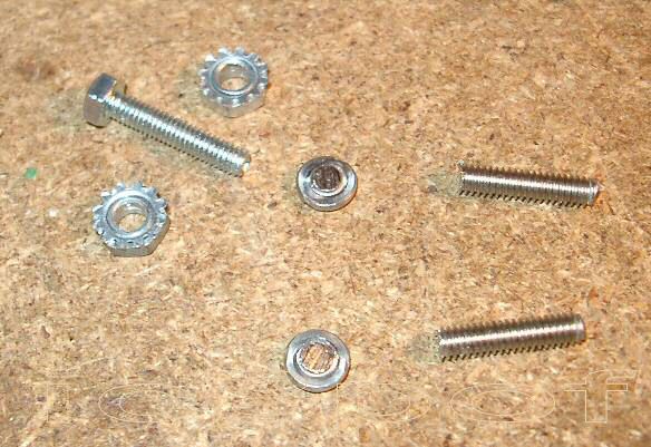
In pic10 are shown : the 2 USA screws with the heads removed . The body will be used to hold the BS.
Between the nuts is the millimetric screw which I had to use to hold the PVC in its place.
As the spacing is given by 2 USA gauge nuts and as I have used a mm screw, I have filed from 2 usa-nuts he grooves as shown in pic9 & 10
to let the usa-nuts give the correct spacing over the mm screw.
Here ends the good-ending story, which has taken about 1 month of working time in january 2006,
The nuts should be stronger but was impossible to find any steel replacement here in I_land.
to have a better band-change feel and lesser stress on the whole switch !
due to the many problems to solve and many months to be written.
Now some improvements not strictly related to the Commander PA,
but easily adapted to any amplifier.
Part 1.
The idea to automate a manual RF amplifier has ran around me from many years.
Follow this link: Crazy Pa Tuner  to read the complete story and its project.
Part 2 .
All PA amplifiers have fans, almost all have noisy fans, rotating at full speed all the time.
The idea was to reduce the speed and the noise during the RX times. These RX times are for me quasi 99%.
At this link : Fan Noise Reducer for any RF amplifier you will read the complete project.
Any improvement or suggestions will be appreciated,
write to my email on ic8pofATyahooDOTcom (copy,paste and correct)
.
*Note1 : after so many years of use in every possible condition I can say that the Commander HF 2500
has one major project error: RTTY on 40meters and few hardware bugs that must be corrected during every day use