* * * Crazy PA Tuner * * *
mod. Cra_PA_Tun I°
How_To transform any manual linear amplifier in an automatic one.
The born of a project from an almost crazy idea.
Introduction.
Since some years I was dreaming of a tuning aid to help me turn the Plate & Tune capacitor knobs of my
manual RF amplifier
when changing the bands especially during the contests.
A sort of RF_PA Auto_Tuner (well semi_auto).
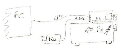
The basic idea was\is to turn the PA knobs with 2 stepper motors(SM) and driven by a software via a PC's port.
In this project the port is the parallel LPT one.
Of course the Band_Switch of the amplifier remains manual, but this is a minor drawback !
From time to time in the last couple of years I have looked and searched in many WWW corners,
but despite many projects there were no one in that Mare_Magnum that fulfilled my idea.
The big problem to solve,as I don't know any programming language, was to find someone possibly
a radioamateur that could write such a piece of software.
One day in nov.2005 my web surfing in search of "steppers" landed on the web pages of Max IK0VVE at www.ik0vve.net
He had just developed a program that turned 2 SM to tune a coil under a short vertical antenna .
It took only few seconds to understand that my search was at the end.
After some emails with Max I was sure to be in touch with the right person.
Max was surprised about my idea, but once he had understood that his software could drive SM in another environment
the Game began. Before all he is a radioamateur, secondly he has the programming knowledge to understand
my requirements and last but not least has the Will to widen the application field of his software.
=.=.=.=.=.=.
This article is divided in 2 main parts : the hardware & pictures are here below and the software help is in this page.
It is not difficult to assemble the hardware.The description will clear many aspects of such contruction.
I was too much curious to see how the project had worked so I have kept the internal and external look at minimum.
Of course the circuit-board could be assembled better and tighter.
But the feel that my Linear Amplifier tuned "alone" (almost...alone) was and is GREAT !
=.=.=.=.=.=.=.=.
The Hardware.
From the dream...to the paper ... to the hardware.
Notes on the interfaces between the SM and the PC ; the RF_PA and the SM.
At the end of the page I will print some links where the hardware can be found.
On the WWW there are many stepper tutorials and projects, but nothing (until now) about the interconnection between the SM
and a manual Power Amplifier or any other equipment that needs to have 1 or 2 knobs rotated into predefined positions.
The only “open-source” project that came near my dream was the EZ_Tuner built by W8ZR Jim.
But this project uses an embedded OS : the BasicStamp of Parallax inc.
I would instead use a software to drive directly the motors.
=.=.=.=.=.=.
Choosing the steppers.
Unipolar models at 0.8A or 1Amp per coil/5Vdc or 6Vdc should be the minimum .
The model I am using is : JAPAN SERVO KP56LM2-097 , its technical specification are:
Unipolar 6 wires / 2 phases ,6 Volts DC (nom) , 1.2 Amps / Phase (nom), 2.4 Amps / Motor, 1.8 Degree/Step, NEMA 23 size.
Here below is a generic stepper schematic.
An important thing to understand, before buying the SM, was to know how much strength should have a SM to
turn the knobs of my amplifier.
These knobs were almost hard to turn and I have never thought about as it seemed to me being normal.
Normal for a human, but not for a machine.
My project had had to drive each VariableCapacitor (VC) via its 6:1 reduction gear, a rubber belt and 2 pulleys.
That meant more strenght than normal turning a VC directly as is in the EZ_Tuner project built by Jim W8ZR.
Having seen that the EZ_Tuner had used some SM of 1Amp\phase at 5Vdc and even if I was nor sure about
the final result
I decided to buy such models.
From a logical point of view almost all SM with phase\coil absorption of less than 0.8Amp\5Vdc were discarded.
DO NOT CONNECT THE COILS DIRECTLY TO THE +VCC. They MUST be driven only by the right pulses.
Of course you can check the coils with an OhmMeter.
Commonly unipolar steppers have 6 wires coded by colors, but can be found also with the 1 and 2 tied together .
More uncommon could be found with all four coils with its own wires i.e. 8 wires .
The 1 & 2 go to +Vdc and the other 4 to its own driving transistor .
Coil wires: be sure to have the right code for each coil wires, otherway will be difficult to get the SM rotating at the first try.
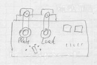
The Box :
I had in my junk an old steel box that had the correct dimensions to mount the SM and let keep the right distances between
the SM and the PA shafts giving the right tension to the belts .
That means the box must have a sufficient height to let the stepper's mounting holes in the panel to be enlarged to find the right tension.
This box must be sufficiently heavy and have rubber feet to absorb the SM vibrations.
The vibrations : You will not know before how will vibrate your steppers and inducting vibrations also to the
linear amplifier box.
So have at hand a piece of rubber to cut the feet and take care about its thickness when deciding the length of the belts.
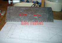
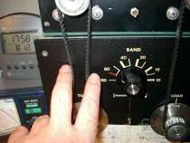
The Front Panel : use at least 2.5mm dick panel.
Knowing all the dimensions it is time to put all the measures on a paper and then mark them on the plate.
The Steppers panel holes :
Once having marked the holes and drilled them on the panel I needed to ovalize them .
This was normal because I had to find the right distance to keep the belts well tensioned.
All the holes bacame very large, almost double the mounting size.
Finding the right distance has taken me more times to screw and unscrew the motors from the panel.
=.=.=.=.=.=.
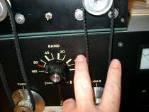
The Steppers direction :
Depending on how the scale on the linear amplifier is marked you will need to let the motors rotate Clockwise or CounterClockwise.
If you see that the counter in the software goes the oppisite direction as the linear's scale then just invert the 4 coils wires of each motor.
=.=.=.=.=.=.
The rubber Belts :
choosing the belts diameter is only a matter of taking a taylor's meter and playing around the PA knobs and the "Crazy PA Tuner" pulleys .
A point to pay attention is the tension of the belts connecting the SM and the VC.
One way to do the first tests with the belt tensioning is putting between the PA and the SM box a book or a magazine,
from which you add or remove the sheets to find the first correct distance.
Than you will notice what would be the right height of the SM on the box front panel.
|
The first "pa" |
The Belt Tension :
This point is important because too much tension of the belts let the SM to loose the driving impulses and not rotating correctly.
This occurrence will be evident already at the first try of the motors.
=.=.=.=.=.=.
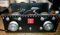
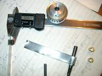
The pulleys:
I have chosen a pulley that has a diameter of 38mm and 20 teeth. The mounting hole is 8mm.
There are also other dimensions, but this one is the nearest to the amplifier's knobs diameter and to the dimensions of the belt I have chosen.
The mounting was at first a little complicated because either the SM and the VC reduction-gear shafts are in inches,about 0,248" or 6.3mm.
I had some brass adapters from 8 to 6 millimeters, but they were too hard to file by hand.
So I had to discover what sort of adapter I should use to enlarge the shafts from 6.3 to 8 millimeters.
Then I remembered to have some steel shim in various thickness.
After some tests I have cut a shim strip and wrapped it onto one 6mm drill head.
This sort of adapter after some tries worked fine so I have built the required pieces: 2 for the SM and 2 for the amplifier's shafts.
|
|
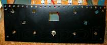
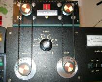
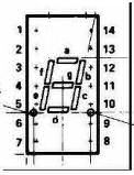
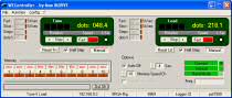
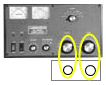
The Display :
I have added 2 LED displays in the middle of the panel for a pure cosmetic purpose, but they helped me at the begin of the Game
to see if the SM coils were connected and rotating in the right sequence .
Each Led-bar goes in parallel with its motor coil.
Any 7 segments display in Common Cathode configuration can be used.
I have had some old HP 5082-7610 a 14 pins DIL package. And have used only the upper 4 bars "a-b-g-f".
As 2 Led bars(ie 2 coils) are to be active at any time I have used a supply resistor of 470Ohm 1/2W for each of the displays.
Much depends on how much brightness you want from the displays.
=.=.=.=.=.=.
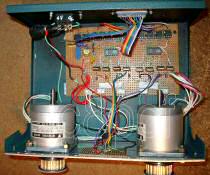
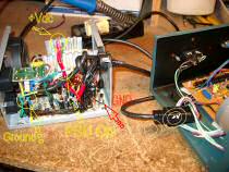
Power Supply :
The current requirements of the running motors (2 coils ON x 2 motors)are circa 4A at +5V, so having no other free Vdc supply I have used a pc ATX-supply
which has plenty of current in the +5Vdc row.
The only doubt was if the impulsive current requirements by the SM were well absorbed by the ATX supply.
After the first try all ran well and the electronic fan in the psu never switches to higer speeds.
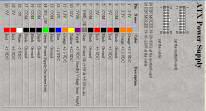
Only 3 wires are needed: +V (reds) , Ground (blacks) and the Power-On at pin 20 (green). Any cable to let flow the current into the steppers box is ok
I have used a spare ATX 220V cable and its socket mounted into the SM box. A fuse of 3 to 5 Amp 220Vac does as safety.
Advice: when cutting Black-Ground wires pay attention that some GND wire has its own short via the wires and not on the board
Look at the tiny black wire marked GND1, it gets the GND on the wires not on the pcb!
|
|
=.=.=.=.=.=.
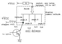
The electrical schematic.
The SM hardware interface used by Max and me is the one that connects the PC's LPT port to the motor coils via optocouplers-ICs-transistors.
Using the OPTOs is the safest mode to get isolated the PC from possible voltage spikes generated by the motors .
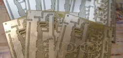
The schematic is very easy to build. link to large schematic
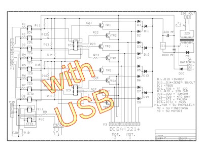 I have built it up on a perforated board 100x160 mm following the components disposition
from the paper to the pcb. Of course the board can be mounted on a smaller pcb, but at the time I was building this one I didn't know how much heat
the transistors had developed, so I placed them with a larger spacing.
I have built it up on a perforated board 100x160 mm following the components disposition
from the paper to the pcb. Of course the board can be mounted on a smaller pcb, but at the time I was building this one I didn't know how much heat
the transistors had developed, so I placed them with a larger spacing.
Now after a couple of weeks playing with the Cra_PA_TunI°, I can say that the transistors are just lukewarm.
So their placement is possible also nearer to each other.
The only change I have made to this schematic has been to omit the protection zeners between the +V and the coils.
The TIP transistors have already an inside protection and the external diode suppresses the possible spikes.
The IC11 & 12 and the relative parts have been left blank in my tuner project as I do not need the limit switches used by Max.
Dic.'06 an  interface has been added for greater flexibility.
It is a www.VELLEMAN.be product model K8055 and is made for pc I\O experiments .
I have purchased it at www.conrad.de
In Italy it is sold by www.FuturaElettronica.it.
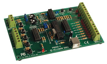
The 8 output lines 01 to 08 of the USB interface are connected to the outputs of the fotocouplers
as marked in the electrical schema.
=================
RFI & S.W.R.
I have had no problems with this project running either LOW, HI power and some SWR on 160 and 80 meters in almost 1 year of use, in dic.'06.
Hardware links:
The rubber belts and the pulleys can be found on http://www.mcmaster.com in USA
and on www.conrad.de in EU under article codes : pulleys nr.226106 and belts nr. 226084 .
Each item has many formats to choose from.
Also RS_Components.in UK or Italy has such items.
The steppers I have used are model: JAPAN SERVO KP56LM2-097 . see above for their characteristics.
=================
The Software.
A very great work has been done by Max IK0VVE.
All of the ideas I have suggested he has translated into working features.
In the pot are melting still more features and they should be added into the new software releases as soon as possible.
In the dedicated page I explain the main controls relative to the Crazy_Tuner part of the software.
=.=.=.=.=.=.
|
Latest NEWS : |
How_To CraPATun.ize an Ameritron: |
|
|
A small quantity of pcbs are ready. gen.09. |
 |
Send to me the pictures of your CraPaTun.ized amplifier and I will add them here in a sort of gallery.
Any improvement or suggestions will be appreciated, do write to my email on ic8pofATyahoodotcom (copy,paste and correct)
.
v1
- gen-mag.06, gen.'07, rev.lug.08, news gen.09, vve link gen.22

this page is hosted on my business domain :