Unfortunately in this period there are not very "Busy Contests" around in which one could try to "fish" weak signals below strong ones.
So having not at my disposition any expensive instruments other than my ears, I was tuning on the bands
to get some crowded channels. I found a commercial rtty station on 10100Khc at s9+ signal strength.
This station is almost every day on the frequency, do not know who is it, but I use it as fishing net.
Under this strong signal from time to time can appear a HAM_CW station
I was trying to receive with the IRF and my cw filters 500 and 250.
But every manoeuvre I have done by switching the IRF unit and the rig's filters on\off no improvement came to my ears.
The only visual & listening difference is the increased noise level when switching ON the IRF unit.
Therefore I prefer to switch OFF the IPO preamplifier to get a quiter ground level when IRF is ON.
Instead of going into the rig's IF_gain menu.
Then I remembered that there was a little program "MPFilters" written by K6SE (find it on va3cr.net) and re-installed it.
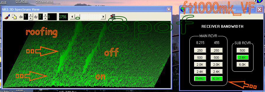
This program lets to receive without the filters or better said with the wide AM passband on ssb (thru at 6khz)
without going into the "DEEP_Functions" of the FT1000 menu.
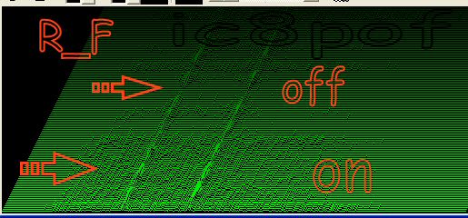
In this wide mode tuning around that rtty signal and playing on\off of my simple switching unit I noticed that
below its center starting about at 2000Hz the signal reduction was audible, but unfortunately the cw station was away.
The screen capture below shows how the tones of the rtty station disappear almost completely when switching ON the IRF unit
starting about 2200Hz away from the main channel.
This band-cut was evident only on the low part of the rtty channel not so on the high side of the tones.
Why so I cannot explain, maybe will do someone more technician than me.
*** Audio file ***
A short mp3 file has been recorded to show the on\off switching of the IRF unit:
roofing-test mp3
The difference will be better understood wearing the headphones.
There are 2 sstv stations the high-pitched is the one that is cutted away when inserting the IRF
The only way to appreciate the narrower IF window of the IRF with the own ears is to switch
the cristal filters off and receiving ssb with the 6khz via the K6SE program.
When using the ssb or cw filters is impossible to appreciate any difference.
* * *
|
* * *
Here is my Point of View after some months of use of the narrower Roofing Filter.
The expectation of better receiving results were great at the beginning ,
but after having tried the IRF in various modes and conditions I have realized that adding
that filter
is not sufficient to beat the close channel QRM specially on 40mt SSB.
CW & Rtty do not take much advantage of the IRF because the tight filters are already sufficient
for a " Ham use ". I suppose that it is a hard battle to obtain a cleaner freq. between
2 ssb stations maybe away only 5 to 8 khcs without modifying deeply the original first IF stages.
... Try to receive in the middle of 2 S9 or stronger stations in ssb ...
... not speaking of those stations ROARing into thier mics at ultra-maximum
because They do not see the meters moving ...
... and Their channel is almost 20 to 50 khcs or even wider ...

Not even mr. Spock could demodulate a qrp station between 2 such "strong" ssb signals !
Hopefully someone of good will and skill one day shall develop and sell a real
*top permormance first IF and Roofing* module
to substitute the original in the FT1000mk_Vx models.
Untill then we can use the VRF, IDBT, Shift&Width, Noise Reduction and RF_Gain
features to improve our receptions.
Yes, RF_Gain control : you will be surprised about this ancient and unused option.
* * * Of course a good Antenna helps ... most of times * * *
In the mean time before we will find a Star_Trek_Enterprise's surplus radio, mount and forget the IRF
added june 2005
|
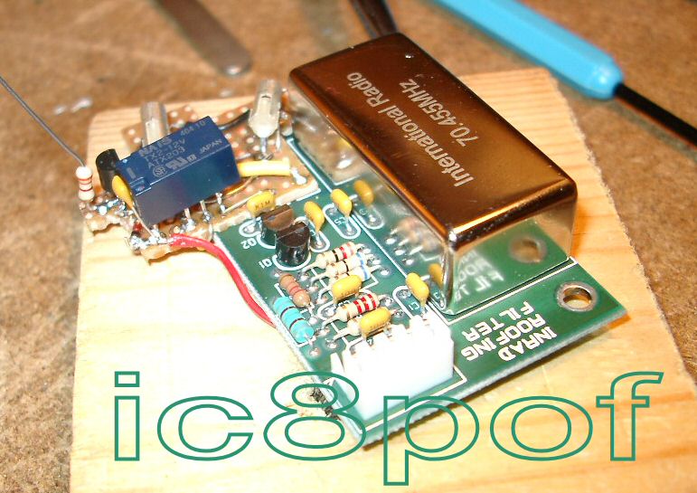
Part one .
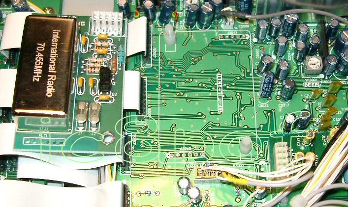
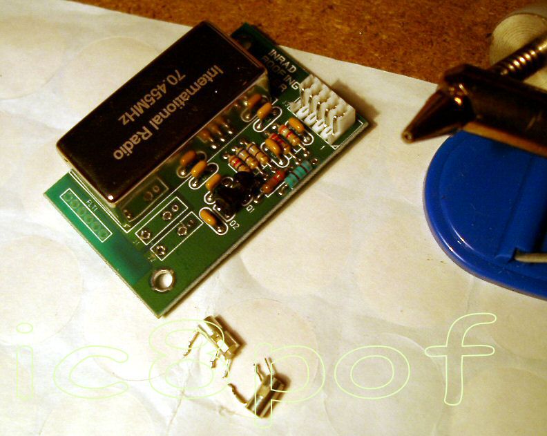
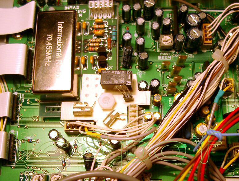
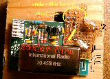
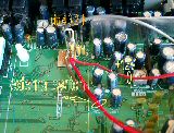
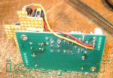
The following serie of pictures show how was the study of the switching board and its mounting into the rig.
The first step was to remove the 2 coaxial plugs J1-J2 and the board studies.

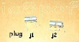

Taking out the 2 miniplugs is a little difficult because they have the legs formed for the snap in montage.
So after desoldering they must be forced a little to come out.Be sure to have removed all the tin.
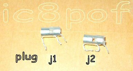
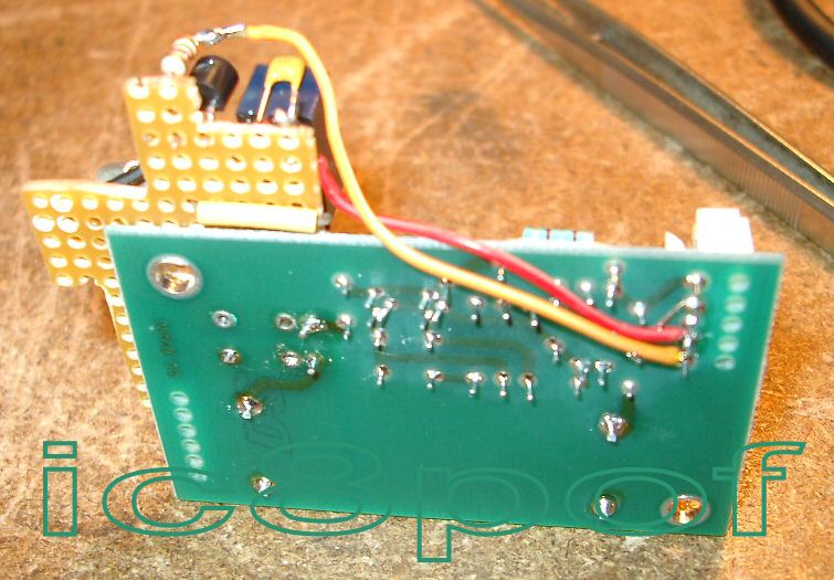
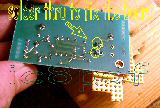
Having decided to solder the components direclty on the copper side I have seen that were much better to bend
the legs of J1 & J2 so they can hold the plug's body with much strenght on the copper pads.
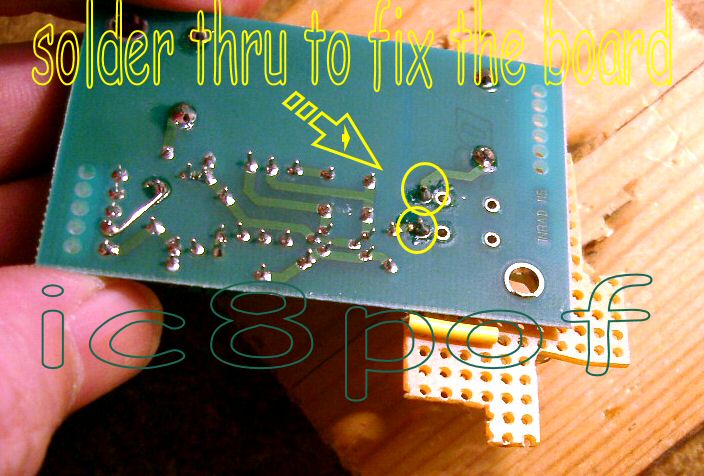
To keep the mini board fixed with the IRF board it is sufficient to solder thru the wires in the holes
where were the 2 J1 and J2 plug as shown in the fotos
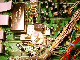
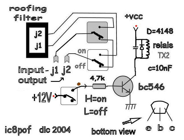
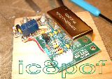
Another problem to solve was how to connect the relais supply voltage and the switching circuitry wires.
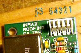
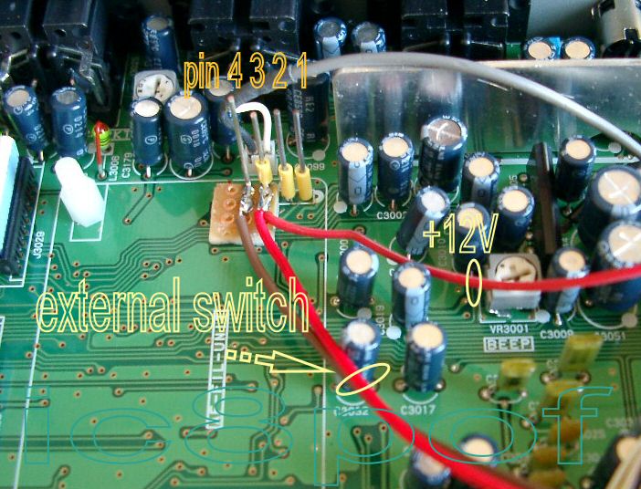
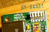
The IRF board is fitted with J3 a 5pin connector, pin1 carries +5V and pin2 the ground to the mini_rf_amplifier, pins 3-4-5 are free.
The switching unit needs 2 more wires : +12V and the positive voltage to pull_up the transistor's base.
This mod. is easier to be done in the mk_V&F than the MP, but with little thinking around and cutting the posts
of pins 3 - 4 and maybe even 5 in the MPs should be done as on the mkV_rigs.
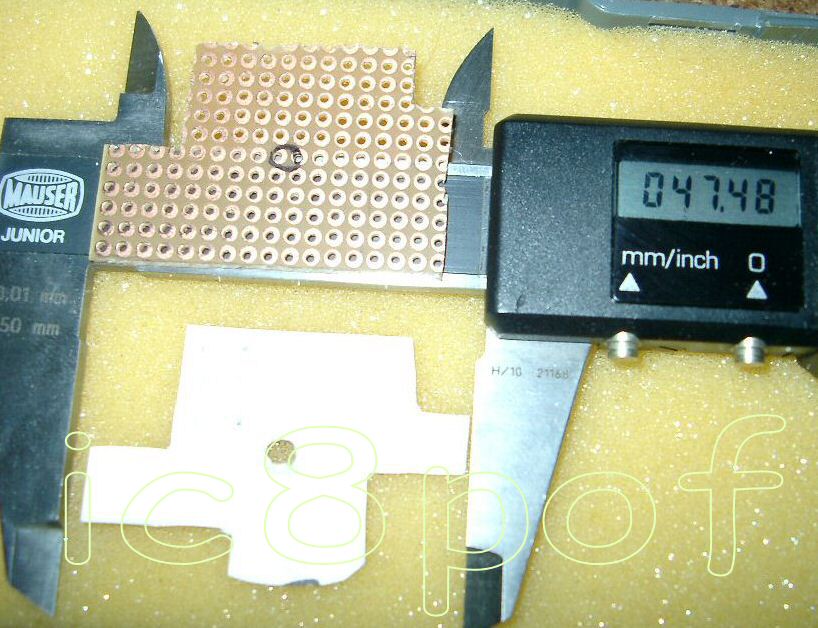
A little piece of double side glued tape will hold in place the small board carrying the pins 3 and 4
�
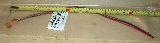
The wires for pin 1-2-3-4 can be cut from a pair of old 2 watt resistors , just try to slip
into j3 pins to feel if it flows well but not to hard. In the pics "step5 & 6" you can see how to add the wires.
The soldering iron should be a small 8W - 12V , taking care in soldering the pins 1 & 2 at maximum 2millimetre
in the AF board. And making very short soldering on those tiny board pad's.
The copper on these boards is not so strong as the copper on normal etching boards.
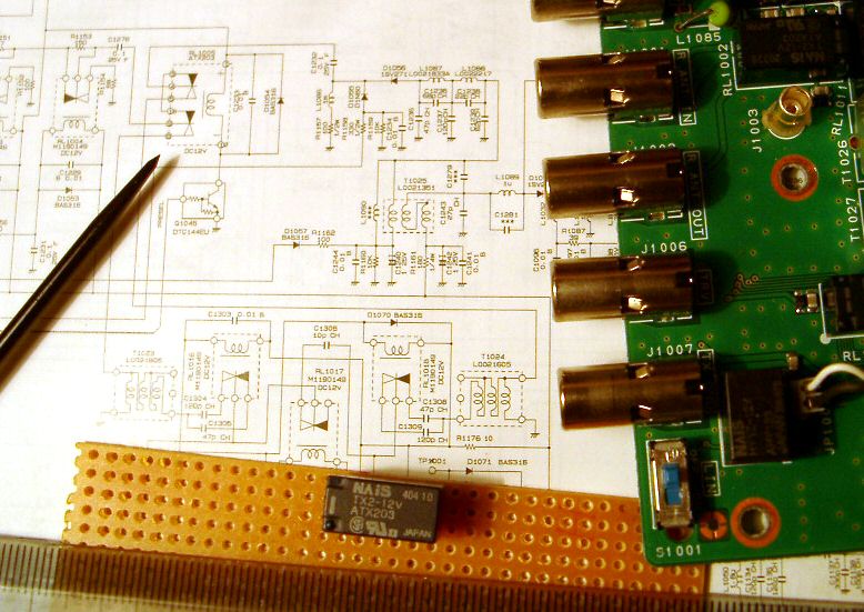
Part two.
Connecting 6 wires and one switch.
Miniboard with pin3 and 4 = "mb"
Wires: w1-red:from j3012 to mb-p3 , w2-red:from j3\p3 to relais TX2 , w3-red:from mb\p3 to external switch about 25cm long
w4-maroon from mb\p4 to external switch , w5-maroon from j3 to resistor 4,7k on the transistor base.
Ground : the ground connection of J1-J2-Emitter can be done directly on the IRF board
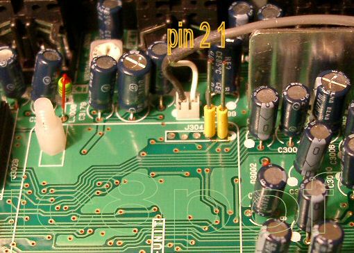
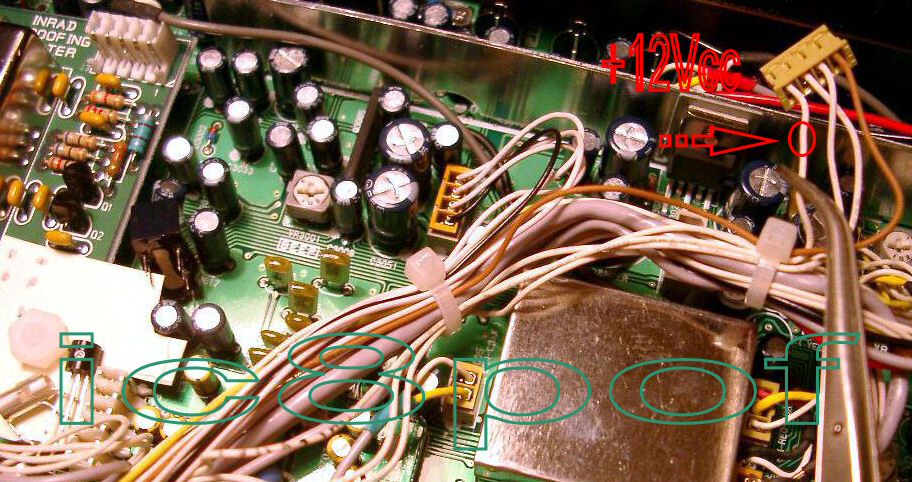
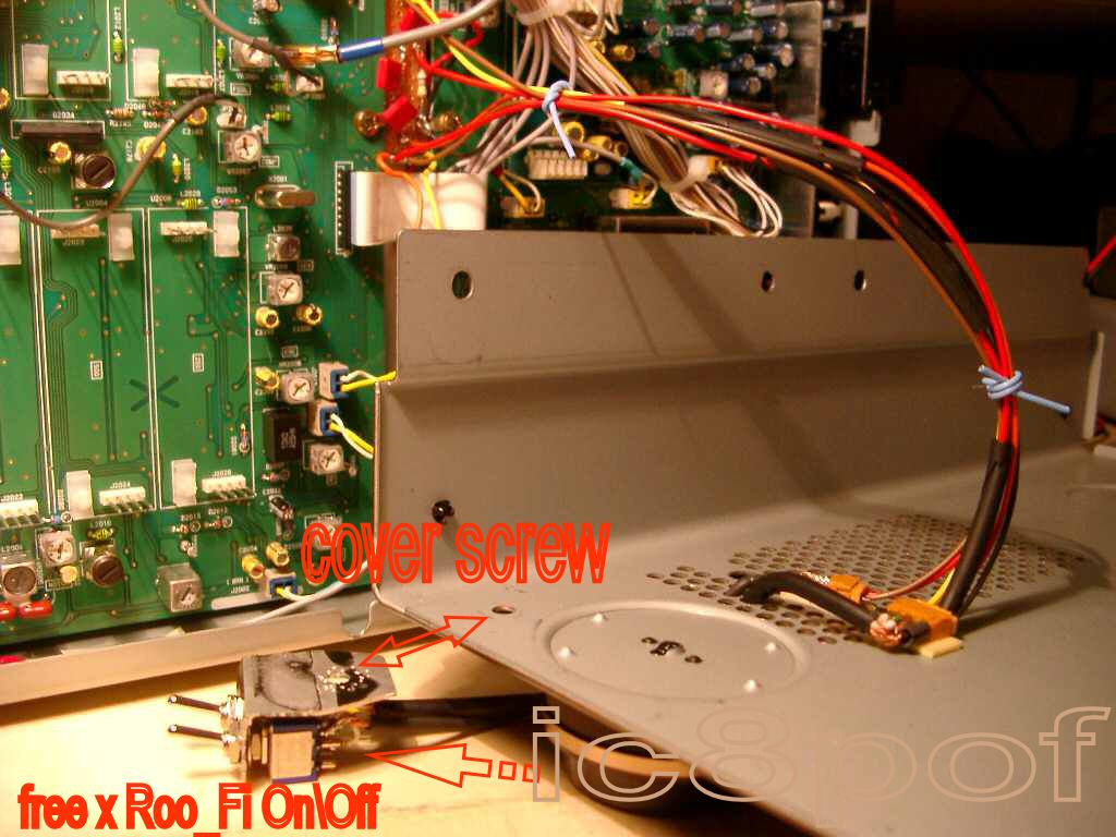
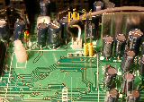
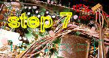
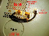
The only easy path where to take the +12Vcc was on J3012 rig's connector, as marked in "step7" fotos.
It lacks to me a foto of the maneuvre, but I will explain how to proceed.
Take the out the connector, with a small clamp keep pulling gently the +Vcc wire.
With a needle free the pin from the socket as marked in the step7 foto by the red circle.
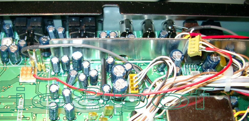
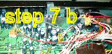
Now carefully with the small iron solder one red piece of wire long enough to go to the mini-board under J3 as shown in "Finish" fotos
Pay attention because the wires are only crimped in the J3012 connector's socket so be very quick to solder the red wire on the +V pin.
Here ends the second part related to the cabling of the mini_switcher to the +Vcc line.
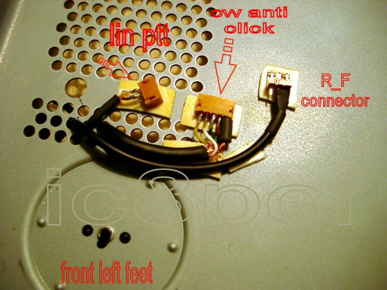
Part three.
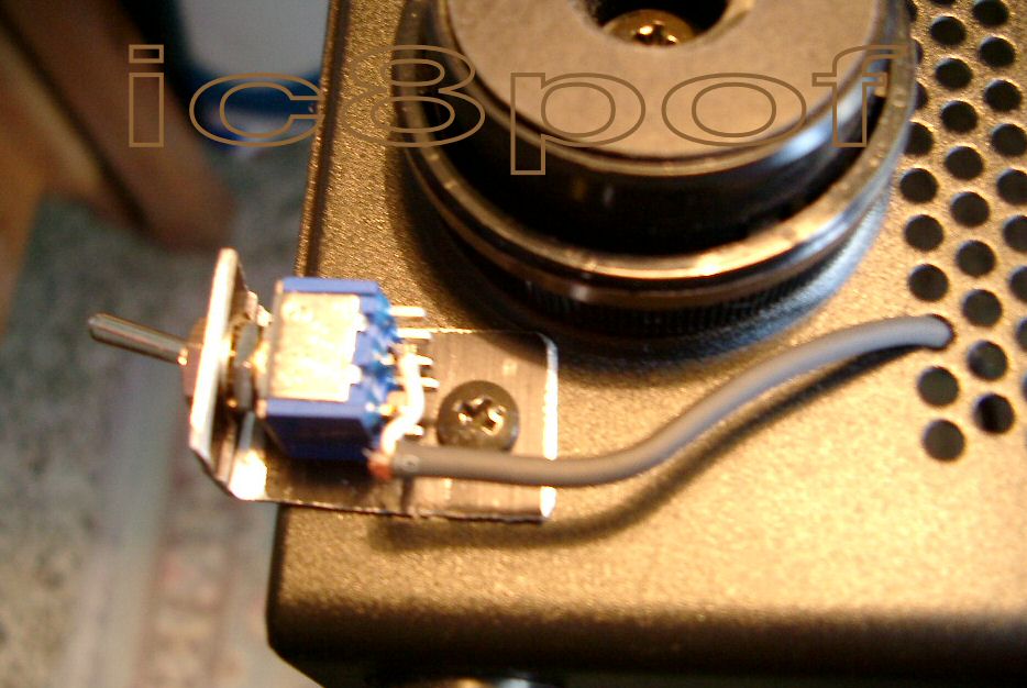
External switch and cabling
Now you can decide to have one , two or more switches on the front of the rig.
I have used both types so can show the 1switch and the 2 switches version
The following fotos show how to mount the connectors and the tiny audio cables to bring on the outside of the rig the signals.


This is all, I do hope I have given a good description for duplicating this small switcher.
Any further improvement or suggestions will be appreciated .
... ...
read the TRUTH on the Roofing Filter bandpass
Visit my Crazy PA Tuner project page 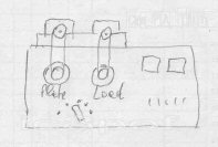
Back to How_To index
Go to IC8POF's main Index page.

this page is hosted on my business domain :
added on dic2004 - feb2005 - giu2005 - mar2006 - gramm-set-dic06, mag09