*
*
*
LA BRACIOLA
*
*
*
click here to hear the right italian pronounce. (n1)
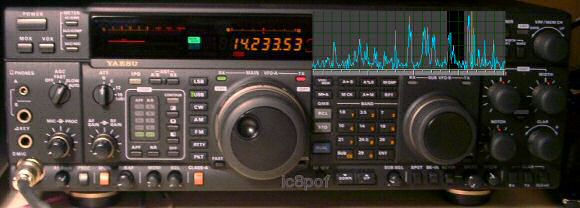
a panorama adapter for any Yaesu FT 1000 MP mkV & Field
but not only, it is possible also on the "old" FT1000 and FT990 ! (n2)
 (n3)
(n3)
Idea : years ago.
The name : from the kitchen to the radio table.
A simple and delicious project.
 this is a view from my RF balcony.
La versione italiana al più presto.
- Project: La Braciola.
- 1) the history,
- 2) the theory,
- 3) the hardware,
- 4) how to use it,
- 5) the examples,
- 6) which SDR,
- 7) why such a name.

Part 1 , the history.
The idea of connecting sometype of equipment in the rig to look at the RF signals around the received frequency as if we were
on a balcony and admire the panorama had flown around me since many years.
Already back in the 1980 I built a little sweeper to connect the oscilloscope to the IF chain of the famous FT101.
Even if the viewable RF window was actractive, the results were not as aspected .
Now many years later the technical state of the art has improved so much that such project led me to give another try
and find an equipment that let me look at the RF signals.
My first attention was attracted by the most modern spectrum analyzers or some sweeper adapters.
Both were expensive anyway and I was quite on the way to give off .
All started again a couple of years ago when a ham friend Jack IC8FAX built a little SDR (software defined radio) with an xtal
tailored for the IF of his FT736 rig with which he succeeded to see a very wide RF window.
That time the new technique was much more performant as in the 1980s.
What impressed me was the very wide RF window viewable at a fraction of the cost of a spectrum analyzer and with many features.
An SDR radio is a sort of direct conversion receiver (n5), from RF to audio in one step and the signals demodulation is made by a
software program in the DSP ic built on any pc sound card.
Among all the normal radio operations :Filtering, NoiseBlanking, NoiseReducing, AGCing, Smetering and a good RF sensitivity
one of the SDR features is that its output bandwidth depends on the sound card used, it can be 24khc for the normal
sound cards or even 48 Khc and 96Khc wide for the professional one.
This is the feature I was looking for: a wide RF window which let me look at a spectrum much larger than the cristal filters of my TRX.
My secret dream was to be able to see at the Roofing Filter window and its characteristics. So it happened !
Therefore I decided to try to use an SDR radio as a wideband IF demodulator.
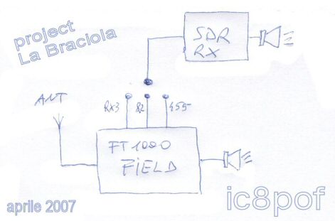
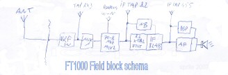
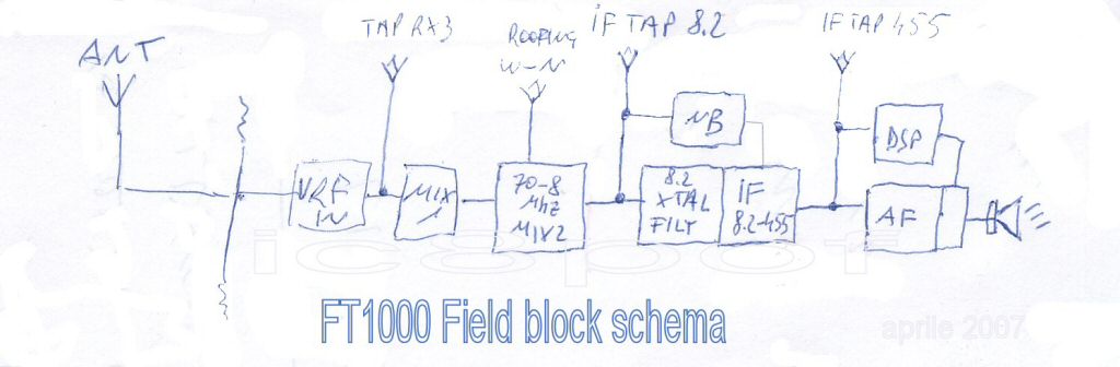
The main idea was to look just at one tap point in the FT1000 Field,
but it ended with a very interesting project
of 3 insertion points available and many many useful options!

Part 2 , the theory .
Even if this project is VERY easy to build up, its description will take some pages (15 for now) to be explained well.
The wide receiving window of the SDR radios has given to me the idea to try to connect such an equipment into the IF chain
of my
FT1000 Field as if it were a spectrum analyzer.
After having examinated the electrical schematic of my rig it revealed not just one, but more points
where to insert the "viewing" taps .
On the way to reopen the rig some doubts and problems occoured :
a) Where and How to add the taps ,
b) if these TAPS had introduced any sort of Interferences in the receiver performance,
c) which SDR radio should be used. Read it in Part 6
d) all the other doubts not clear before the project.
- WHERE : the tap insertion points were discovered quite easy, the problem was how to do them.
- 1st IF is 70Mhz. This tap could show a very wide RF window,
but the VHF circuitry and the cost of an SDR receiving above 30Mhz led me to discard this option.
- 2nd IF is 8.2Mhz , this tap is easier to add even if it is in someway difficult to reach and to attach,
- 3rd IF is 455Khc , this one is easy as it has already a dedicated check point for testing purposes.
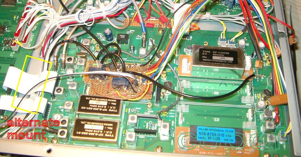
- Location: there is a lot of space in the bottom Field's room to add a small pcb
but the easiest way would be to use an empty IF filter place.
First because it is near the through hole for passing the 8.2Mhz coax and second because the small perf.board seats
perfectly
on the filter's connectors, whose keep in place the new switching unit.
If you have all the filters in place ... then take one off ;-) , or move the new pcb around the room
in a place nearest to the
8.2Mhz tap. That would be between the IF Unit and the Control Unit.
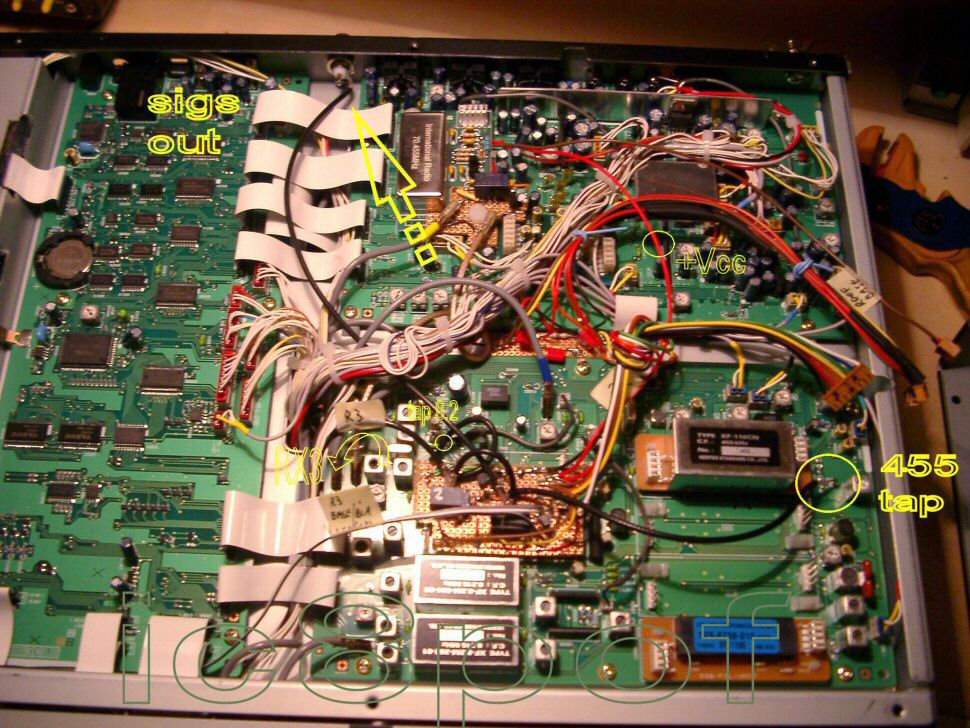
Look at pic nr.2 where is placed a yellow X .
- HOW :
- It was quite evident that the IF signals could not be pulled together. A sort of switching circuit should be added.
- A small PCB with a couple of relays came in mind, as I already used such a circuit in the Roofing Filter Unit.
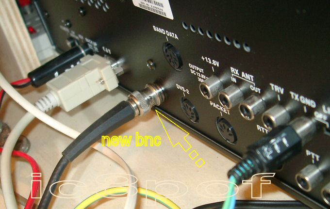
- of course these switched signals had to be brought out of the rig. Here comes the need of the only hole to be drilled
to mount a BNC connector which will give the passthrough way to the RF signals.
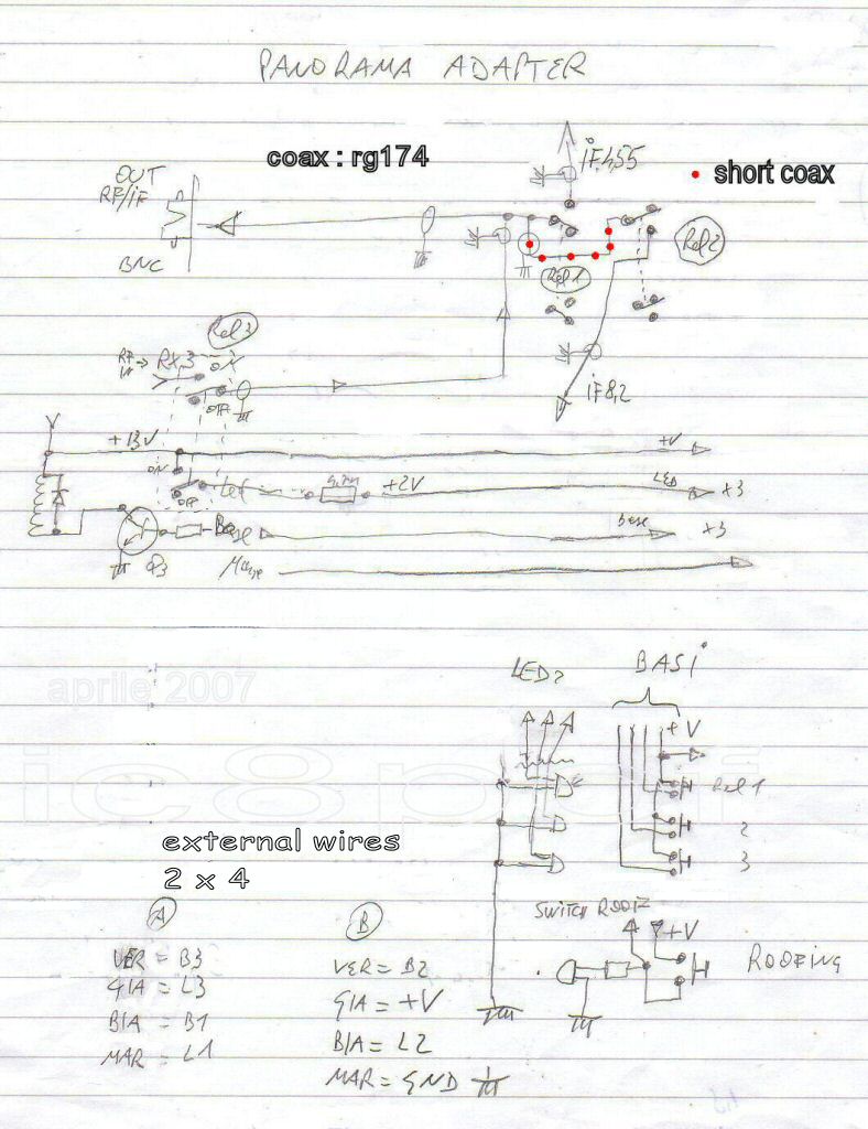
The main schematic, the pcb and the BNC output location are shown below :
 link
link
 link
link
 link(n4)
It is not a complicated device.
- The TAPs :
- Looking at the schematic of my FT1000mkV_Field I noticed a point very close to the 1st IF
but already mixed down at 8.2Mhz.
This is the output signal from the 2nd IF mixer at the Noise Blanker tap.
Here it is possible to observe the RF_window coming out from the famous Roofing Filters .
The panorama tap is in parallel to the Noise Blanker output.
 NBtap
NBtap
- The second tap is quite at the 455Khc output just before the signals go into the DSP unit of the rig.
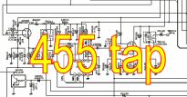 455Khc tap
- The Interferences :
-
Of course I have monitored the IF frequencies at 8.215 Mhz and 455Khc+-25Khc with the general coverage receiver for
some times to be sure that
there were not strong BC stations around.
Otherway there could be more or less interferences in the IF rig's chain requiring a more isolated RF switching circuit
which could complicate a lot my simple project.
The triple tap monitoring system via the switching relays circuit could also give some interferences .
But as for many Ham things: if not sure then test it !
This time the Fortune assisted me in giving no interference at all.
- The Doubts :
- As for all the things after the theorical studies comes the time to put them in practice .
As there are always many doubts about a new project, my suggestion is : make it and try!
During the test period of the IF Taps on my rig another idea led my mind ...
- ... a GREAT Idea : 3rd RX in the FT1000mk_V_Field
-
Using an SDR radio as an external demodulator or as a panorama viewer is fine, but is limiting its main functions.
Of course with an outside RF relay we could use it as an external normal receiver, but this is a too simple case.
- Why not use this radio directly in the RX RF\VRF chain of my rig and use it as if it were a 3rd receiver ?
- A great feature : SDR radio with preselector.
- As the SDR radios have very wide input RF circuits I thought that connecting it after the Field's RF\VRF
input Filters
could give to such a rig a big improvement in its receiving characteristics
and give
to me one more opportunity of an external receiver with which to listen and compare the received signals.
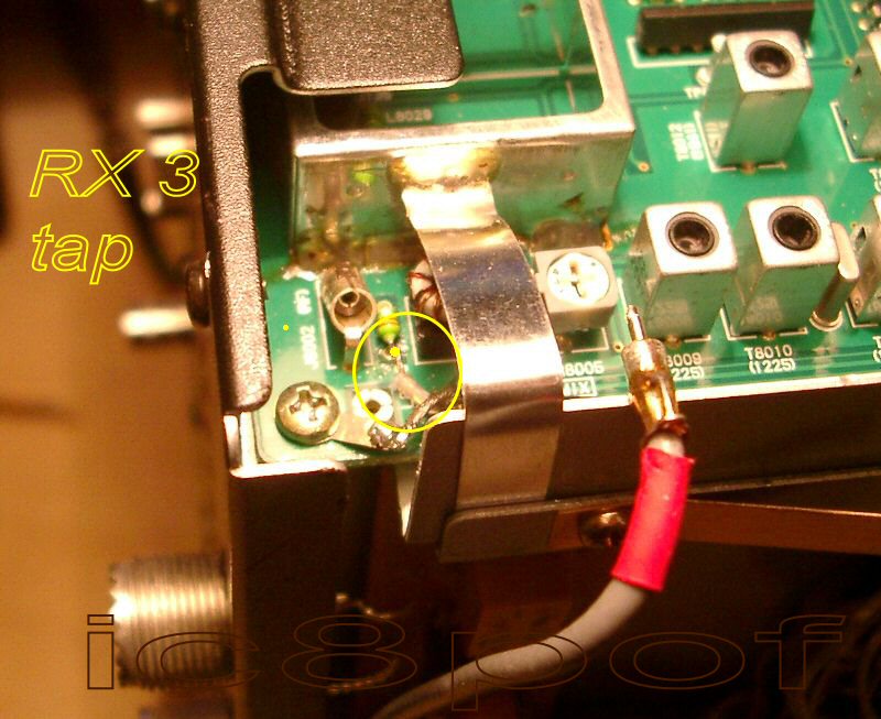
- The insertion Tap for the RX3 is quite in parallel to the already RF signal input to the 2nd RX.
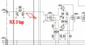 RX 3 tap
- To not complicate the IF Taps unit I have used a second small pcb with its swtching components
direclty in the RX2 unit.
- This mod. is easier to add as to describe.
Part 3 , the hardware .
The pictures show the main mounting steps for this simple "La Braciola" panorama adapter.
- The work in the rig can be divided into 6 steps :
- 1) BNC connector mount,
- 2) mounting the taps at 8.2Mhz and 455Khc ,
- 3) mounting pcb1 with relay nr.1 and 2 ,
- 4) mounting pcb2 with relay nr.3 ,
- 5) mounting the interconnecting wires and +Vcc\Gnd
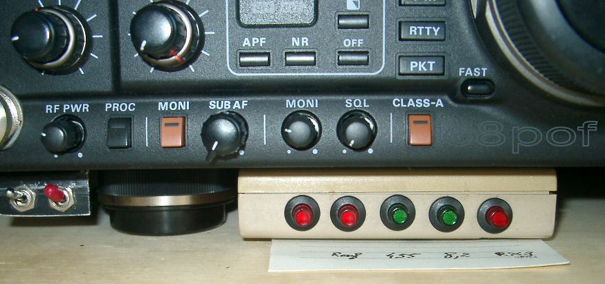
- 6) mounting the external box with the switches.
- 7) the parts list.
Having all the goals clear I decided that it was time to work in the rig .
To come inside the rig both covers are to be opened.
As the need asks for turning the rig on the table for better working and viewing put it on a magazine.
Look at my HowTo access into the rig page for more info.
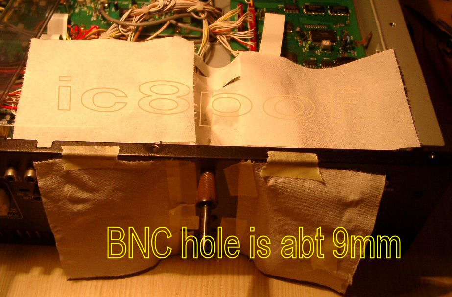
P3-Step 1 , the BNC Hole .
Of course care MUST be taken to do a clean work. Look at pics 2-3-4.
The strip cable near the back panel must be taken away and placed in a secure place.
As the BNC hole is about 9mm do first a 3mm hole and pass to 5 and 7 or 8mm.
To get 9mm file it by hand so the BNC seats firmly in the hole.
P3-Step 2a , the 8.2Mhz tap .
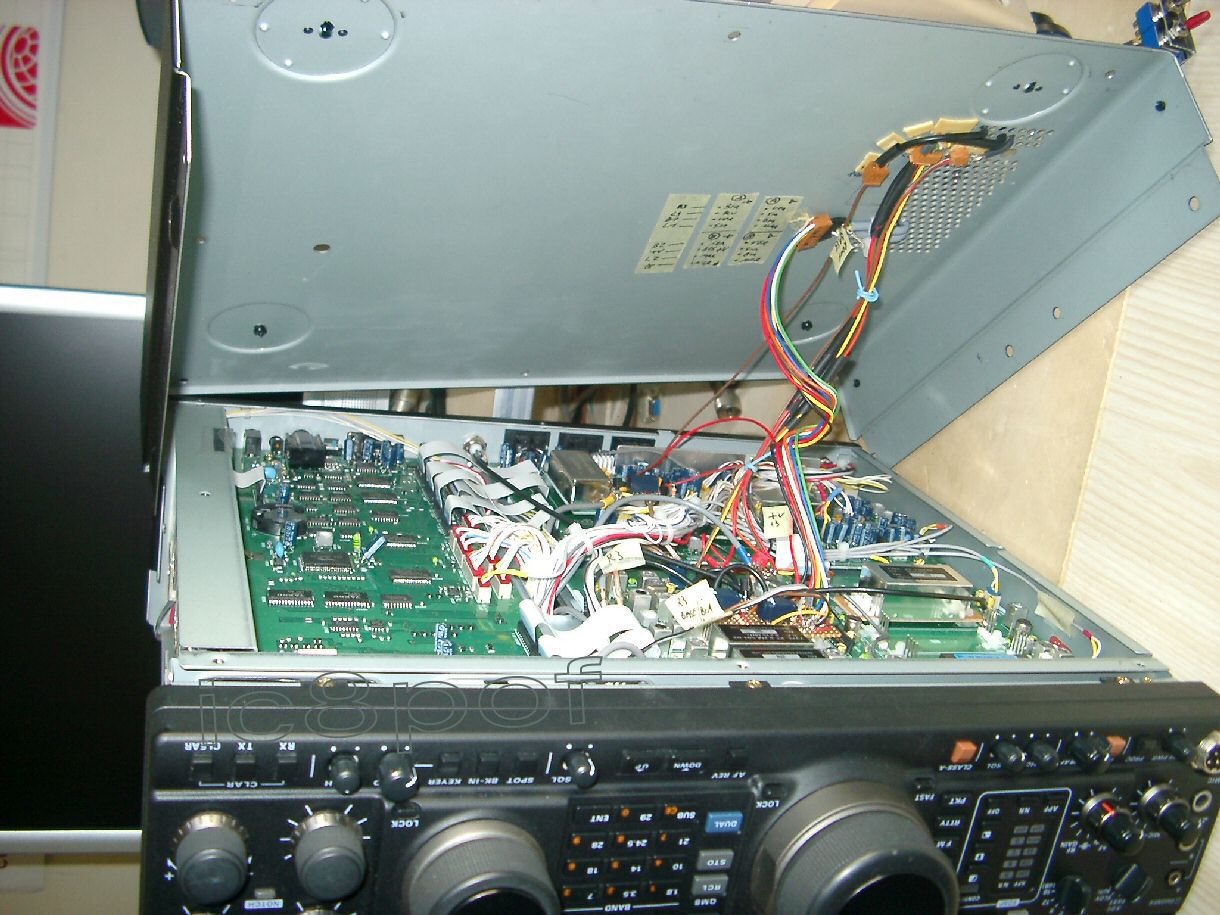
The main work is on the IF unit located on the underside of the rig.
This unit MUST be taken out.
Look at the Cables pic below. It is an easy job, all the coax cables are color coded .
Pull the coaxes and the strips gently but firmly,
 remove cables
The 3 strip control cable pulled out only from the IF Unit.
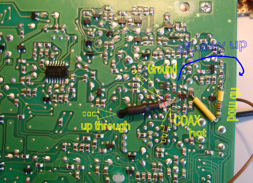
The next step is to mount the tap on 8.2Mhz IF on the underside of the IF unit.
In the pic nr.5 there is an enlarged pic-crop, look at it with any imaging program,
there is a small yellow point indicating where to solder the inner cable of the coax.
The coax is routed up through a filter feet-pad.
There was no other short way to take outside the RF signals as pics 5 and 6 show .
Should you have the filter installed in that place, you can route the coax cable on the side out (blu wire in pic 6)
and up for a little longer piece of cable. The switching pcb may be mounted between the IF and Control units.
If you have not yet done , it is a good time to add the W8JI Noise Blanker mod.
P3-Step 2b , the 455Khz tap .
This tap is very easy to add. Locate it on the above Cables picture on its right side.
A short piece of coax to relais 1 on PCB1. That is all.
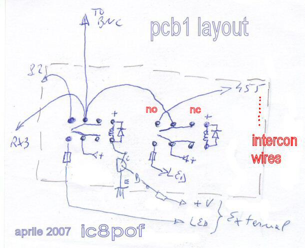
P3-Step 3 , the PCB 1 .
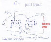 layout
Look at cables pic. . This pcb has DIL raster 2.54mm.
I have mounted it with the pads turned up for practicalness and passes perfectly on the xtal filter connectors.
Each xtal connector has 3 pins grounded, on one per side you can solder the PCB1 to keep it firmly.
- On this pcb, look at the Schema pic above, find place :
- the relay 1 + 1 diode 1n4148 on the coil,for the 455Khc tap : 1 pole to the coax and the 2nd pole to the signalling led .
- the relay 2 for the 8.2Mhz tap, same as rel1,
- the switching transistors for Rel1 & 2 with the base resistor.
- the coax coming from Relay 3 and its switching wires
- the 8 output wires to the outgoing switcheries : 6 signals and +V and Ground.
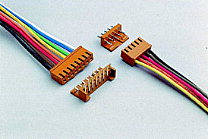 model 741256\8poles by www.conrad.de
- 2 wires per transistor toward the outside: one for the base and one for the signal led.
The +V connection has given to me some doubts on the possibility to carry the power up for 2 more relays.
As I have already a tap on the +V for the Roofing filter I have prolonged this connection also to the PCB1 for supplying
the +V for the relays the leds and the switching for the Roofing Filter in the outside box.
Should you make a NEW +V connection take a look at my Roofing filter web page .
P3-Step 4 , the RX3-PCB2 .
- On this pcb find place the relay 3 with its components for switching in & out the RF signals
coming from the RF filters via the red-coax of the FT1000 mkV Field rig and going to the SDR radio.
- The antenna tap must be soldered on the small blocking inductor as shown on pic 8
Use a small soldering iron, about 8W, and be precise and quick as the soldering area is very small.
- The +V for the relay is taken from J8001 at pin 4. Be very careful and quick to solder the wire on
that pin as the Yaesu wires are only crimped.
- The Ground posts can be done near the Ground screws, one at the relay and one at the coax RF input.
- The switching and the led wires may be routed through the chassis junction until the PCB 1 interconnection cables
P3-Step 5 , the interconnection wires .
- From the inner to the external side of the chassis may be used two of the vent holes.
I have used a 4pole + ground audio cable, dividing the 8 poles into 2 cables of about 30cm.
- The holes have been enlarged to let the cables pass through and secured with plastik strips.
 the underside.
- Care should be payed to the colours of the cables.
P3-Step 6 , the external box & switches .
- The box dimensions depend mostly on what switches you will have at hand,
the only mandatory dimension
is its height MAX 25mm.
- It is fastened with a double sided scotch tape about 2cm inside the front to not protrude too much
on the front of the rig.
 external connections.
 model nr.701243 by www.conrad.de.
- This item has double function : pushbutton + switch, with signal led.
P3-Step 7 , the parts list .
- 1 BNC panel connector, only one hole of 9mm is to be drilled,
- 120cm RG174 coax,
- 3 relays TX2 model nr.504788 by www.conrad.de
same as the ones used in the Field or equivalent for HF, low power double pole,
- 3 transistors BC546 npn or equiv.,
- 3 diodes 1N4148,
- 6 resistors 4k7ohm 1/4w,
- 4x12 cm perf-board with round copper pads DIL spacing 2,54 ,
- some centimetres of connecting wire various colors.
- 80 cm audio coax with 4 poles ,
- 3 mini-switches\push-button single pole with signal-led like model nr.701230 by www.conrad.de or equivalent,
- 1 plastic box 10cm wide x 5cm depth x 23mm maximum high,
- any SDR radio with DDS-vfo.
- as you are going to open the rig it is strongly advisable that you mount the switching unit for your Roofing filter
- so add a 4th group of : 1 transistor, 1 relay, 1 switch, 2 resistors 1 diode.
- and of course : the famous INRAD Roofing filter if you still havent it !
Part 4 , HowTo use the Panorama adapter.
After having connected a coax between the SDR radio and our FT1000 Field via the new BNC output and connected
it to the pc,
in my case an Usb cable to the CiaoRadio RX and launched the software, in the main window of the SDR
we are faced to the normal front panel of a receiver.
After having Config_ured the software you can tune the SDR rx to the IF frequency of our rig at 8.215 Mhz
push on the relative 8.2 switch and on the SDR display you will look at the first panoramic view of your RF window.
Having set the audio in the Config menu you will also be able to listen to the signals you are tuning with your rig
coming out from the pc speakers.
The final center frequency will depend on how you listen at the ssb signals.
The function of the 455Khc Tap is the same as the 8.2, only here the passband is relative to the xtal filters used in the IF.
More, it is possible to see how the controls SHIFT & WIDTH work on both IF taps.
FINE very FINE !
Only one attention : the 8.2 tap is phase inverted. That means that USB\Field will be listened in LSB\SDR and viceversa.
This is not a problem as we can put the IF frequency to whatever QRG we want and also memorize it.
A new world of possibilities opens ahead of our eyes : viewing splatters on 5 to 10Khz wide ssb stations,
cw-clicks, checking and comparing signals,
seeing running jammers on the band, ... Ooooooooo_LAh singers ....,
etcetera ...etcetera ...
but what surprised me has been the possibility to look at the transmitted signals, either SSB (mic-gain & proc. adjustments) and CW.
The first indeep test of the "La Braciola" I have done during the 2007 CQ-WPX-ssb on 160M.
No problems at all either in rx and tx.
The biggest surprise has come when I have seen for the first time the passband of the roofing filters
and the differences between the Yaesu and the Inrad roofing filters.
I will publish these impressions in a separate page under the Roofing Filter HowTo web pages.
Part 5 , some examples.
Some of the infinite panoramic views are shown here.
Rtty panorama on 20mt.
Rain on the HF2V on 160m.
wide 1250 pixels display on 160mt.
40 meters 3d view. A RF view plus 3d audio of an ssb station.
the TRUTH on the Roofing Filter bandpass.
Part 6 , which SDR Radio ?
I have discarded the xtal controlled SDRs as they do not permit to move freely the center frequency
as is possible with the DDS\Vfo.
On the market there are many SDR radios, but not being sure of the results and not wanting to spend much money I have
chosen an
italian product called CIAORadio-H101 model.
A rig developed by Hams and involved in specialized comunications.
This link will bring you to their web pages for more infos on their product.
It is a very complete baseband receiver, beside its bandpass-filters it has also a 16bit/24khz sound card on board,
the USB connection carries the signals and powers the unit.
There are two antenna inputs, RF Attenuator, step variable IF amplification, mute on TX.
The filter width is selectable in steps and freely with the mouse.
The NB works very well, but it lacks (hope for short time) of a Noise Reduction feature.
The NOTCH feature is very complete, it is actuated with the mouse and is VERY effective.
- Two complaints:
- the demodulated audio is delayed too much in respect to the same signal of the Yaesu Field rig.
- the audio on strong signals is often stretched.
Anyway a really FINE piece of equipment !
More: the display of the CiaoRadio can be pulled on the whole width of the monitor, in this way all the signals are quasi zoomed in !
Very interesting feature.
I have already given many suggestions to the developers of CiaoRadio to make better use of this product
in a real HAM environment .
One fantastic feature would be the frequency syncronisation via the CAT system between the mkV_Field and the CiaoRadio.
With a wagon full of new features. One for all the tracking of the DX speditions working in split.
Of course any other SDR radio can be used.
Anyone of you that will use other SDR models with the FT1000 MP mkV Field is invited to let me know his experiences
and I will create a comparison table
with the differences between the models and their functions.
Part 7 , the name La Braciola .

La Braciola is a typical plate of the Italian kitchen. One day I will add also my recipe of this plate.
There are many ways to cook it, but the more important characteristic is that it has few ingredients and more it cooks
more it is good.
From this peculiarity comes the name of my "La Braciola" pan-adapter project.
So even if I am not a good cook (nor a technician in the electronic field)
I have cooked\assembled a very fine plate\project with few ingredients but with many many possibilities to use it
in the Ham field.
Have a lot of fun in looking from our personal balcony
at the RF panorama with La Braciola.
Any improvement or suggestions will be appreciated, do write to my email on ic8pofATyahoodotcom (copy,paste and correct)
- Foot notes :
- n1) a special list of La Braciola Fans will be published with your pronounce as soon as you build up this project.
- n2) for the "ol' FT1000 " cousins , this project is easy mountable on this radio too.
A look at its service manual showed that it is easy to add the mod. .
For the FT990 I am not sure , but as the rig is similar to the 1000 it should be also possible.
Please let me to know about.
- n3) this picture is real only in my imagination.
- n4) In the pics PCB and nr.10 beside the pan-adapter wires there are some more going out:
- one connector carries out the base wire to activate the Inrad roofing,
- one other is an external switch to ON or OFF the click_reducing mod. made by W8JI,
- and one wire is in parallel to the rear switch LIN_PA.
- n5) There are many references on the web for the SDR radios specifications, ARRL in primis.
I leave to you the task of searching for them.
Reading and viewing suggestions: as this document is 15 pages long, save the whole project in a folder of your HD
and print it on the paper so you can read it almost everywhere ... ;-))
Back to How_To index
Go to Index page.
© v.1 ott.2007, apr.2009, rev2.30, link mag'20,

these pages are hosted on my business domain.
 link
link
 link
link
 link(n4)
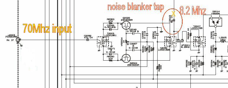 NBtap
NBtap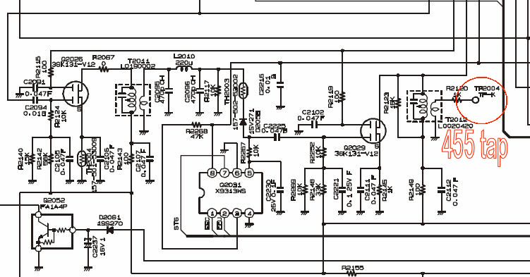 455Khc tap
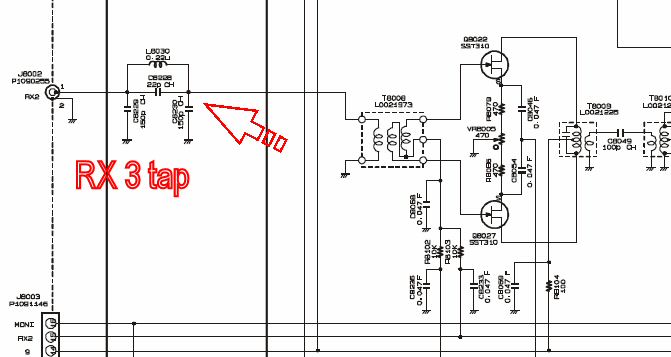 RX 3 tap
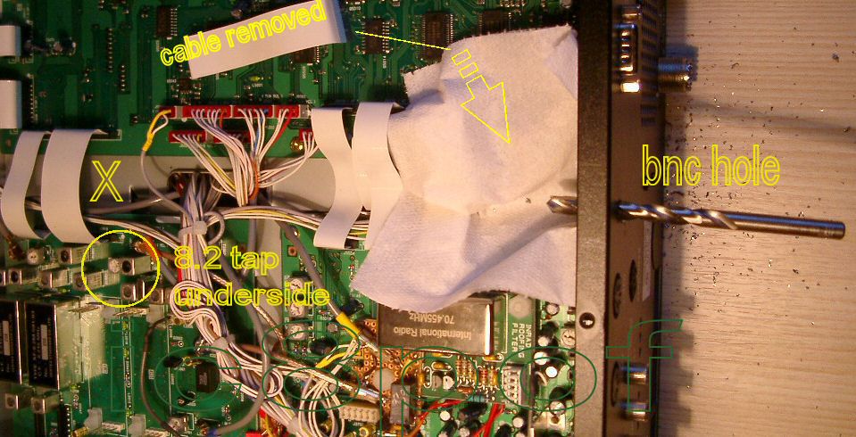
 remove cables
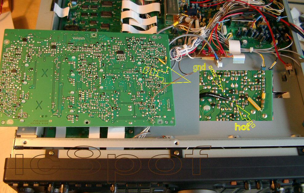
 layout
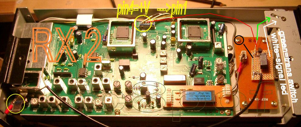
 the underside.
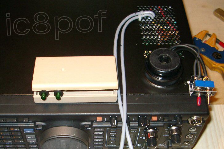 external connections.